
The 64-bit Standalone Plan 9 File Server
Ken Thompson*
ken@plan9.bell-labs.com
Geoff Collyer
geoff@plan9.bell-labs.com
Bell Laboratories
Murray Hill, New Jersey 07974
ABSTRACT
This paper is a revision of Thompson’s The Plan 9 File Server, and describes the structure and the operation of the new 64-bit Plan 9 file servers. Some specifics apply to the 32-bit Plan 9 file server Emelie, which code is also the basis for the user-level file server kfs.
In 2004, Collyer created a 64-bit version of Thompson’s 32-bit file server, updating all file offsets, sizes and block numbers to 64 bits. In addition, triple- and quadruple-indirect blocks were implemented. File name components were extended from 27 to 55 bytes. This code is also the basis for the user-level file server cwfs(4).
Introduction
The Plan 9 file server Emelie is the oldest piece of system software still in use on Plan 9. It evolved from a user-level program that served serial lines on a Sequent multi-processor. The current implementation is neither clean nor portable, but it has slowly come to terms with its particular set of cranky computers and devices.
The file server fs64 runs a revision of Emelie’s code with 64-bit file sizes, offsets and block numbers and indirect blocks from single to quadruple. Actually these are 63-bit values, since the type used is vlong (signed long long integer), but 63 bits should suffice for a little while.
Process Structure
The Plan 9 file system server is made from an ancient version of the Plan 9 kernel. The kernel contains process control, synchronization, locks, and some memory allocation. The kernel has no user processes or virtual memory.
The structure of the file system server is a set of kernel processes synchronizing mostly through message passing. In fs64 there are 27 processes of 11 types:
The server processes
The main file system algorithm is a set of identical processes named srv that honor the 9P protocol. Each file system process waits on a message queue for an incoming request. The request contains a 9P message and the address of a reply queue. A srv process parses the message, performs pseudo-disk I/O to the corresponding file system block device, formulates a response, and sends the response back to the reply queue.
The unit of storage is a logical block (not physical sector) of data on a device:
enum
{
RBUFSIZE = 8*1024
};
typedef vlong Off;
typedef
struct
{
short pad;
short tag;
Off path;
} Tag;
enum
{
BUFSIZE = RBUFSIZE - sizeof(Tag)
};
typedef
struct
{
uchar data[BUFSIZE];
Tag tag;
} Block;
All devices are idealized as a perfect disk of contiguously numbered blocks each of size RBUFSIZE. Each block has a tag that identifies what type of block it is and a unique id of the file or directory where this block resides. The remaining data in the block depends on what type of block it is.
The srv process’s main data structure is the directory entry. This is the equivalent of a UNIX i-node and defines the set of block addresses that comprise a file or directory. Unlike the i-node, the directory entry also has the name of the file or directory in it:
enum
{
NAMELEN = 56,
NDBLOCK = 6,
NIBLOCK = 4,
};
typedef
struct
{
char name[NAMELEN];
short uid;
short gid;
ushort mode;
short wuid;
Qid qid;
Off size;
Off dblock[NDBLOCK];
Off iblocks[NIBLOCK];
long atime;
long mtime;
} Dentry;
Each directory entry holds the file or directory name, protection mode, access times, user-id, group-id, and addressing information. The entry wuid is the user-id of the last writer of the file and size is the size of the file in bytes. The addresses of the first 6 blocks of the file are held in the dblock array. If the file is larger than that, an indirect block is allocated that holds the next BUFSIZE/sizeof(Off) block addresses of the file. The indirect block address is held in iblocks[0]. If the file is larger yet, then there is a double indirect block that points at indirect blocks. The double indirect address is held in iblocks[1] and can point at another (BUFSIZE/sizeof(Off))2 blocks of data. This is extended through a quadruple indirect block at iblocks[3] but the code is now parameterised to permit easily changing the number of direct blocks and the depth of indirect blocks, and also the maximum size of a file name component. The maximum addressable size of a file is therefore 7.93 petabytes at a block size of 8k, but 7.98 exabytes (just under 263 bytes) at a block size of 32k. File size is restricted to 263−1 bytes in any case because the length of a file is maintained in a (signed) vlong. These numbers are based on fs64 which has a block size of 8k and sizeof(Off) is 8.
The declarations of the indirect and double indirect blocks are as follows.
enum
{
INDPERBUF = BUFSIZE/sizeof(Off),
};
typedef
{
Off dblock[INDPERBUF];
Tag ibtag;
} Iblock;
typedef
{
Off iblock[INDPERBUF];
Tag dibtag;
} Diblock;
The root of a file system is a single directory entry at a known block address. A directory is a file that consists of a list of directory entries. To make access easier, a directory entry cannot cross blocks. In fs64 there are 47 directory entries per block.
The device on which the blocks reside is implicit and ultimately comes from the 9P attach message that specifies the name of the device containing the root.
Buffer Cache
When the file server is booted, all of the unused memory is allocated to a block buffer pool. There are two major operations on the buffer pool. Getbuf will find the buffer associated with a particular block on a particular device. The returned buffer is locked so that the caller has exclusive use. If the requested buffer is not in the pool, some other buffer will be relabeled and the data will be read from the requested device. Putbuf will unlock a buffer and if the contents are marked as modified, the buffer will be written to the device before the buffer is relabeled. If there is some special mapping or CPU cache flushing that must occur in order for the physical I/O device to access the buffers, this is done between getbuf and putbuf. The contents of a buffer is never touched except while it is locked between getbuf and putbuf calls.
The file system server processes prevent deadlock in the buffers by always locking parent and child directory entries in that order. Since the entire directory structure is a hierarchy, this makes the locking well-ordered, preventing deadlock. The major problem in the locking strategy is that locks are at a block level and there are many directory entries in a single block. There are unnecessary lock conflicts in the directory blocks. When one of these directory blocks is tied up accessing the very slow WORM, then all I/O to dozens of unrelated directories is blocked.
Block Devices
The block device I/O system is like a protocol stack of filters. There are a set of pseudo-devices that call recursively to other pseudo-devices and real devices. The protocol stack is compiled from a configuration string that specifies the order of pseudo-devices and devices. Each pseudo-device and device has a set of entry points that corresponds to the operations that the file system requires of a device. The most notable operations are read, write, and size.
The device stack can best be described by describing the syntax of the configuration string that specifies the stack. Configuration strings are used during the setup of the file system. For a description see fsconfig(8). In the following recursive definition, D represents a string that specifies a block device.
D = (DD...)
This is a set of devices that are concatenated to form a single device. The size of the catenated device is the sum of the sizes of each sub-device.
D = [DD...]
This is the interleaving of the individual devices. If there are N devices in the list, then the pseudo-device is the N-way block interleaving of the sub-devices. The size of the interleaved device is N times the size of the smallest sub-device.
D = {DD...}
This is a set of devices that constitute a ‘mirror’ of the first sub-device, and form a single device. A write to the device is performed, at the same block address, on the sub-devices, in right-to-left order. A read from the device is performed on each sub-device, in left-to-right order, until a read succeeds without error, or the set is exhausted. One can think of this as a poor man’s RAID 1. The size of the device is the size of the smallest sub-device.
D = pDN1.N2
This is a partition of a sub-device. The sub-device is partitioned into 100 equal pieces. If the size of the sub-device is not divisible by 100, then there will be some slop thrown away at the top. The pseudo-device starts at the N1-th piece and continues for N2 pieces. Thus pD67.33 will be the last third of the device D.
D = fD
This is a fake write-once-read-many device simulated by a second read-write device. This second device is partitioned into a set of block flags and a set of blocks. The flags are used to generate errors if a block is ever written twice or read without being written first.
D = xD
This is a byte-swapped version of the file system on D. Since the file server currently writes integers in metadata to disk in native byte order, moving a file system to a machine of the other major byte order (e.g., MIPS to Pentium) requires the use of x. It knows the sizes of the various integer fields in the file system metadata. Ideally, the file server would follow the Plan 9 religion and write a consistent byte order on disk, regardless of processor. In the mean time, it should be possible to automatically determine the need for byte-swapping by examining data in the super-block of each file system, though this has not been implemented yet.
D = cDD
This is the cache/WORM device made up of a cache (read-write) device and a WORM (write-once-read-many) device. More on this later.
D = o
This is the dump file system that is the two-level hierarchy of all dumps ever taken on a cache/WORM. The read-only root of the cache/WORM file system (on the dump taken Feb 18, 1995) can be referenced as /1995/0218 in this pseudo device. The second dump taken that day will be /1995/02181.
D = wN1.N2.N3
This is a SCSI disk on controller N1, target N2 and logical unit number N3.
D = hN1.N2.0
This is an (E)IDE or *ATA disk on controller N1, target N2 (target 0 is the IDE master, 1 the slave device). These disks are currently run via programmed I/O, not DMA, so they tend to be slower to access than SCSI disks.
D = rN1
This is the same as w, but refers to a side of a WORM disc. See the j device.
D = lN1
This is the same as r, but one block from the SCSI disk is removed for labeling.
D = j(D1D2*)D3
D1 is the juke box SCSI interface. The D2’s are the SCSI drives in the juke box and the D3’s are the demountable platters in the juke box. D1 and D2 must be w. D3 must be pseudo devices of w, r, or l devices.
For w, h, l, and r devices any of the configuration numbers can be replaced by an iterator of the form <N1-N2>. N1 can be greater than N2, indicating a descending sequence. Thus
[w0.<2-6>]
is the interleaved SCSI disks on SCSI targets 2 through 6 of SCSI controller 0. The main file system on Emelie is defined by the configuration string
c[w1.<0-5>.0]j(w6w5w4w3w2)(l<0-236>l<238-474>)
This is a cache/WORM driver. The cache is three interleaved disks on SCSI controller 1 targets 0, 1, 2, 3, 4, and 5. The WORM half of the cache/WORM is 474 jukebox disks. Another file server, choline, has a main file system defined by
c[w<1-3>]j(w1.<6-0>.0)(l<0-124>l<128-252>)
The order of w1.<6-0>.0 matters here, since the optical jukebox’s WORM drives’s SCSI target ids, as delivered, run in descending order relative to the numbers of the drives in SCSI commands (e.g., the jukebox controller is SCSI target 6, drive #1 is SCSI target 5, and drive #6 is SCSI target 0).
The read-ahead processes
There are a set of file system processes, rah, that wait for messages consisting of a device and block address. When a message comes in, the process reads the specified block from the device. This is done by calling getbuf and putbuf. The purpose of this is the hope that these blocks will be used later and that they will reside in the buffer cache long enough not to be discarded before they are used.
The messages to the read-ahead processes are generated by the server processes. The server processes maintain a relative block mark in every open file. Whenever an open file reads that relative block, the next 110 block addresses of the file are sent to the read-ahead processes and the relative block mark is advanced by 100. The initial relative block is set to 1. If the file is opened and only a few bytes are read, then no anticipating reads are performed since the relative block mark is set to 1 and only block offset 0 is read. This is to prevent some fairly common action such as
file *
from swamping the file system with read-ahead requests that will never be used.
Cache/WORM Driver
The cache/WORM (cw) driver is by far the largest and most complicated device driver in the file server. There are four devices involved in the cw driver. It implements a read/write pseudo-device (the cw-device) and a read-only pseudo-device (the dump device) by performing operations on its two constituent devices the read-write c-device and the write-once-read-many w-device. The block numbers on the four devices are distinct, although the cw addresses, dump addresses, and the w addresses are highly correlated.
The cw-driver uses the w-device as the stable storage of the file system at the time of the last dump. All newly written and a large number of recently used exact copies of blocks of the w-device are kept on the c-device. The c-device is much smaller than the w-device and so the subset of w-blocks that are kept on the c-device are mapped through a hash table kept on a partition of the c-device.
The map portion of the c-device consists of blocks of buckets of entries. The declarations follow.
enum
{
BKPERBLK = 10,
CEPERBK = (BUFSIZE - BKPERBLK*sizeof(Off)) /
(sizeof(Centry)*BKPERBLK),
};
typedef
struct
{
ushort age;
short state;
Off waddr;
} Centry;
typedef
struct
{
long agegen;
Centry entry[CEPERBK];
} Bucket;
Bucket bucket[BKPERBLK];
There is exactly one entry structure for each block in the data partition of the c-device. A bucket contains all of the w-addresses that have the same hash code. There are as many buckets as will fit in a block and enough blocks to have the required number of entries. The entries in the bucket are maintained in FIFO order with an age variable and an incrementing age generator. When the age generator is about to overflow, all of the ages in the bucket are rescaled from zero.
The following steps go into converting a w-address into a c-address. The bucket is found by
bucket_number = w-address % total_buckets;
getbuf(c-device, bucket_offset + bucket_number/BKPERBLK);
After the desired bucket is found, the desired entry is found by a linear search within the bucket for the entry with the desired waddr.
The state variable in the entry is one of the following.
enum
{
Cnone = 0,
Cdirty,
Cdump,
Cread,
Cwrite,
Cdump1,
};
Every w-address has a state. Blocks that are not in the c-device have the implied state Cnone. The Cread state is for blocks that have the same data as the corresponding block in the w-device. Since the c-device is much faster than the w-device, Cread blocks are kept as long as possible and used in preference to reading the w-device. Cread blocks may be discarded from the c-device when the space is needed for newer data. The Cwrite state is when the c-device contains newer data than the corresponding block on the w-device. This happens when a Cnone, Cread, or Cwrite block is written. The Cdirty state is when the c-device contains new data and the corresponding block on the w-device has never been written. This happens when a new block has been allocated from the free space on the w-device.
The Cwrite and Cdirty blocks are created and never removed. Unless something is done to convert these blocks, the c-device will gradually fill up and stop functioning. Once a day, or by command, a dump of the cw-device is taken. The purpose of a dump is to queue the writes that have been shunted to the c-device to be written to the w-device. Since the w-device is a WORM, blocks cannot be rewritten. Blocks that have already been written to the WORM must be relocated to the unused portion of the w-device. These are precisely the blocks with Cwrite state.
The dump algorithm is as follows:
a) The tree on the cw-device is walked as long as the blocks visited have been modified since the last dump. These are the blocks with state Cwrite and Cdirty. It is possible to restrict the search to within these blocks since the directory containing a modified file must have been accessed to modify the file and accessing a directory will set its modified time thus causing the block containing it to be written. The directory containing that directory must be modified for the same reason. The tree walk is thus drastically restrained and the tree walk does not take much time.
b) All Cwrite blocks found in the tree search are relocated to new blank blocks on the w-device and converted to Cdump state. All Cdirty blocks are converted to Cdump state without relocation. At this point, all modified blocks in the cw-device have w-addresses that point to unwritten WORM blocks. These blocks are marked for later writing to the w-device with the state Cdump.
c) All open files that were pointing to modified blocks are reopened to point at the corresponding reallocated blocks. This causes the directories leading to the open files to be modified. Thus the invariant discussed in a) is maintained.
d) The background dumping process will slowly go through the map of the c-device and write out all blocks with Cdump state.
The dump takes a few minutes to walk the tree and mark the blocks. It can take hours to write the marked blocks to the WORM. If a marked block is rewritten before the old copy has been written to the WORM, it must be forced to the WORM before it is rewritten. There is no problem if another dump is taken before the first one is finished. The newly marked blocks are just added to the marked blocks left from the first dump.
If there is an error writing a marked block to the WORM then the dump state is converted to Cdump1 and manual intervention is needed. (See the cwcmd mvstate command in fs(8)). These blocks can be disposed of by converting their state back to Cdump so that they will be written again. They can also be converted to Cwrite state so that they will be allocated new addresses at the next dump. In most other respects, a Cdump1 block behaves like a Cwrite block.
Sync Copy and WORM Copy Processes
The scp process wakes up every ten seconds and issues writes to blocks in the buffer cache that have been modified. This is done automatically on important console commands such as halt and dump.
The wcp process also wakes up every ten seconds and tries to copy a dump block from the cache to the WORM. As long as there are dump blocks to copy and there is no competition for the WORM device, the copy will continue at full speed. Whenever there is competition for the WORM or there are no more blocks to copy, then the process will sleep ten seconds before looking again.
The HP WORM jukebox consists of 238 disks divided into 476 sides or platters. Platter 0 is the A side of disk 0. Platter 1 is the A side of the disk 1. Platter 238 is the B side of disk 0. On Emelie, the main file system is configured on both sides of the first 237 disks, platters 0-236 and 238-474.
9P Protocol Drivers
The file server described so far waits for 9P protocol messages to appear in its input queue. It processes each message and sends the reply back to the originator. There are groups of processes that perform protocol I/O on some network or device and the resulting messages are sent to the file system queue.
There are two sets of processes ethi and etho that perform Ethernet input and output on two different networks. These processes send Ethernet messages to/from two more processes ilo and ilt that do the IL reliable datagram protocol on top of IP packets.
The last process in Emelie, con, reads the console and calls internal subroutines to executes commands typed. Since there is only one process, only one command can be executing at a time. See fs(8) for a description of the commands available at the console.
Acknowledgements
Ken Thompson created the Plan 9 file server and maintained it for many years. The cached WORM driver is based upon Sean Quinlan’s PhD. thesis and prototype. Jim McKie maintained the IBM-PC-dependent code, a thankless job. Bruce Ellis modified the 8c compiler in 2004 to generate much faster code for common vlong operations, which made the 64-bit file server feasible. Nigel Roles contributed support for the APC UPS and the NCR/Symbios/LSI-Logic SCSI host adaptors.
References
[1] Sean Quinlan, ‘‘A Cached WORM File System,’’ Software—Practice and Experience, Vol 21., No 12., December 1991, pp. 1289-1299.
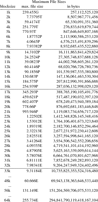
Appendix: Maximum File Sizes in the 64-bit File Server
The maximum size of a single file in a Plan 9 file server’s file system with 64-bit block numbers is determined by the file system block size (there are single, double, triple and quadruple indirect blocks). The maximum size is thus d(6+x+x2+x3+x4) bytes, where d=blocksize−(2+2+8) and x’0-0.85m’x=b’���’8dl’50u-0.2m’b’���’x’1.05m’, 8 being the size in bytes of a long long block number.
Note that 263 = 9,223,372,036,854,775,808 = 8 EB (binary exabytes).
Notes
l’4i’
* now
ken@google.com